Instrumented Crankset
Instrumented Crankset
Introduction
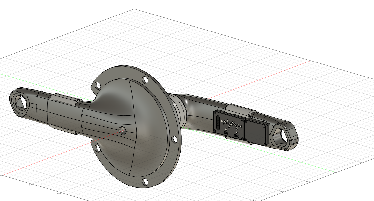
The Phyling V2 instrumented crankset integrates a high-precision sensor capable of measuring, at high frequency (200 Hz), the forces applied to each crank arm, the angular velocity, the cadence and the power developed by the cyclist.
In this new version, the Mini-Phyling is now fully autonomous:
- it embeds its sensor configuration and its calibration file;
- it connects automatically to the various visualization systems (Maxi-Phyling, bike computers and sports watches);
- it can be used immediately, without any prior manual configuration.
This evolution greatly simplifies field deployment while guaranteeing consistent accuracy, whatever reading device is used.
Acquisition chain
Instrumenting your crankset comes with several elements that together form a complete acquisition chain:
- a force sensor on the left and right crank arms;
- a standalone acquisition unit connected to the sensor: the Mini-Phyling;
- a central multi-connection acquisition unit: the Maxi-Phyling (optional);
- a cloud application for data processing, analysis and visualization.
General characteristics
| Characteristic | Value |
|---|---|
| Dimensions | 86.1 mm × 30 mm × 11 mm |
| Weight | 20 g |
| Battery life | 5 hours |
| Data transfer | Wired or BLE via Maxi-Phyling |
| Charging | Magnetic cable with no risk of being torn off |
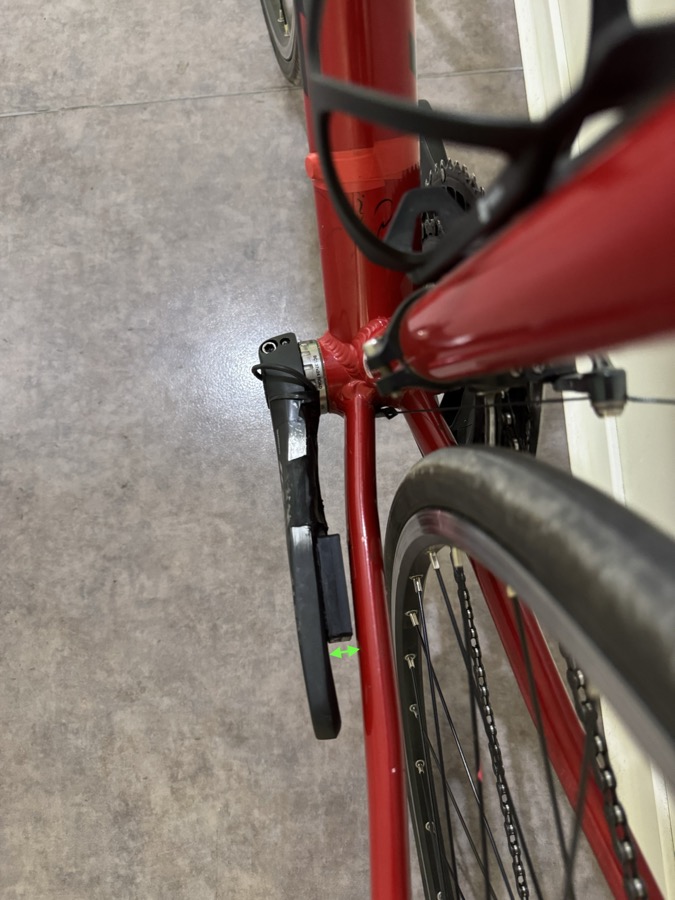
| Minimum frame / crank clearance | 15 mm at the closest point between the frame and the crank arm opposite the drivetrain (see the image below) |
Phyling Cycling / BMX application
The Phyling Cycling / BMX application was developed in collaboration with the FFC (French Cycling Federation) and the French national track cycling and BMX teams, in order to provide accurate analysis of the markers and performance indicators specific to these disciplines.
It allows coaches and technical staff to:
- get detailed feedback on training;
- visualize, compare and process data;
- export results as reports;
- share data with training tracking platforms such as Nolio.
Real-time visualization is possible thanks to a Maxi-Phyling connected to the crankset's Mini-Phyling. All the data is then available as customizable indicators and charts.
Quick start
This section describes the main ways of using the Phyling instrumented crankset.
Mode 1 — Mini-Phyling only (standalone)
This mode lets you record a session without any external device.
- Turn on the Mini-Phyling on the crankset with the ON button (green LED).
- Start recording with the REC button.
- At the end of the session, stop recording with the REC button.
The data is stored locally in the Mini-Phyling.
To retrieve the data:
- turn off the Mini-Phyling;
- press and hold ON until the yellow LED lights up;
- connect the magnetic cable to a computer.
A MINI_XXX folder appears; it contains the recordings, numbered chronologically.
Ideal for: track competitions, simple protocols, use without any infrastructure.
Mode 2 — With Maxi-Phyling (optional)
This mode enables centralized recording and real-time visualization.
- Turn on the Mini-Phyling on the crankset.
- Turn on the Maxi-Phyling on the bike.
- Wait for the automatic connection between the Mini-Phyling and the Maxi-Phyling (light blue blinking).
- Start recording on the Maxi-Phyling with the REC button (blue LED).
- Press REC again to stop recording (green LED).
The data is saved in the Maxi-Phyling, then uploaded to the application via USB or Wi-Fi.
Ideal for: structured training, field tests, scientific monitoring.
Mode 3 — Real-time visualization via the cloud application (optional)
This mode enables live remote monitoring.
- Turn on the Mini-Phyling and the Maxi-Phyling.
- Connect the Maxi-Phyling to a Wi-Fi source (smartphone hotspot, 4G router, local network).
- Go to the application at https://app.phyling.fr.
- Log in with your username and password.
- Open the Real time tab to view the data live.
Ideal for: remote monitoring by coaches and sports directors.
Mode 4 — With a bike computer or sports watch (optional)
The Mini-Phyling V2 can be used directly with a bike computer or a sports watch compatible with Bluetooth Low Energy (BLE).
- Turn on the Mini-Phyling.
- From your computer or watch, search for a new power sensor.
- Select the Mini-Phyling.
Power and cadence are displayed in real time.
Ideal for: daily training, competition, use on the go.
Data processing and export
Recordings are available in the Data tab of the Phyling application.
- Associate your recordings with the New button.
- View a session, create selections and compare several recordings.
- Export your data in various formats: PDF report, raw data, CSV files.
Data
The data recorded and computed for cycling and BMX provides information about performance (torque, cadence, power, etc.), both instantaneous and averaged per pedaling cycle.
To take full advantage of these measurements, Phyling provides access to the raw data of each sensor and offers dedicated analyses for computing advanced indicators.
The tables below describe the computed variables and indicators, as well as how they are obtained.
Sampling frequencies
| Sensor | Frequency |
|---|---|
| Crankset | 200 Hz |
CSV file data
This data is found in the CSV file that can be downloaded from the application. It is time-series data sampled at 200 Hz, including both raw and computed data. This is also the data displayed as charts in the application.
| Variable | Description | Unit | Calculation |
|---|---|---|---|
| T | Time since the start of the recording | s | |
| Gyro | Crankset angular velocity (gyroscope) | rad/s | 0.5 s moving average (0.05 s in BMX) and offset subtraction |
| F_g | Left force | N | 0.025 s moving average and offset subtraction |
| F_d | Right force | N | 0.025 s moving average and offset subtraction |
| mag | Magnetometer signal (once-per-revolution marker) | Raw data | |
| Cadence_G | Cadence (gyroscope) | rpm | Gyro |
| motif_id | Unique identifier for each pedaling cycle | Cycle detection based on the magnetometer signal if present, otherwise based on F_g | |
| Cadence | Corrected cadence | rpm | Obtained by combining the gyro cadence and the once-per-revolution cadence (in BMX: Cadence = Cadence_G) |
| F_tot | Total force | N | F_g + F_d |
| Couple | Total torque | Nm | F_tot (crank length) |
| Couple_g | Left torque | Nm | F_g (crank length) |
| Couple_d | Right torque | Nm | F_d (crank length) |
| Puissance | Power | W | Couple Cadence |
| Puissance_g | Left power | W | Couple_g Cadence |
| Puissance_d | Right power | W | Couple_d Cadence |
| Vitesse | Speed | km/h | Cadence dev 1e-3 60 (fixed gear) with dev = gear ratio circ (in BMX, if dev is not provided, GPS speed is used) |
| D | Distance traveled | m | By integration of the speed |
| Theta | Crank angle | deg | By integration of the angular velocity and mapping onto [0, ] (not available in BMX) |
| SCx | SCx | m² | See calculation below |
| Couple_mean | Mean torque per pedaling cycle | Nm | mean(Couple) |
| Puissance_mean | Mean power per cycle | W | mean(Puissance) |
| Balance | Right/left balance (right leg share, 50 % = balanced) | % | mean(Puissance_d) / (mean(Puissance_g) + mean(Puissance_d)) 100 |
| timestamp | Timestamp since 1970 | s | Based on the Maxi-Phyling time |
SCx calculation
The SCx is calculated using the following formula:
Warning
This formula is only valid when the bike is riding at constant speed, on flat ground, with no wind.
It is derived from the power balance:
with:
- : power delivered by the athlete;
- : transmission efficiency (typically between 0.95 and 0.99);
- , where is the air density;
- , where is the total mass (cyclist + bike) and the rolling resistance coefficient (typically between 0.002 and 0.006 depending on the tires and pressure).
Indicators
Indicators are statistics characterizing a selection of data. They appear in the Indicators table of the application as well as on the first page of PDF reports.
Track cycling
| Variable | Description | Unit | Calculation |
|---|---|---|---|
| P_max | Max mean power | W | max(Puissance_mean) |
| Cad_Pmax | Cadence at Pmax | rpm | Cadence[i_Pmax] |
| Cad_max | Max cadence | rpm | max(Cadence) |
| Couple_max | Max torque | Nm | max(Couple) |
| PCR7 | Max mean torque over 7 s | Nm | max(7 s moving average) |
| PPRx | Max mean power over x s | W | max(x s moving average) |
BMX
| Variable | Description | Unit | Calculation |
|---|---|---|---|
| V_max | Max speed | km/h | max(Vitesse) |
| Cad_max | Max cadence | rpm | max(Cadence) |
| P_max | Max instantaneous power | W | max(Puissance) |
Calibration
Calibration with Maxi-Phyling
Calibrating the crankset with the Maxi-Phyling is an essential step to ensure the accuracy of force measurements. It uses a guided calibration module built into the Phyling application, which simplifies the process by automating the linear regression calculations. Results are expressed in Newtons for optimal compatibility with cycling analysis in the application.
Prerequisites
To perform a complete and accurate calibration, you need:
- a bike mounting system that holds the bike horizontally (along the wheelbase axis) and vertically (with a 0-degree tilt), without any movement;
- calibrated weights covering a minimum range of 0 kg to 30 kg (examples: 0 kg, 10 kg, 20 kg, 30 kg);
- an attachment system to hang the weights at the center of the pedal axle;
- a magnet fixed on the frame where the Mini-Phyling passes, for once-per-revolution detection;
- a Maxi-Phyling connected over Wi-Fi to access the guided calibration module on the Phyling cloud application;
- a Mini-Phyling connected to the Maxi-Phyling via a wireless link.
Step 1: Access the calibration module
- Open the Phyling cloud application CF app cloud lien.
- Go to the Real time tab.
- Locate your Maxi-Phyling and click the three vertical dots (
⋮) next to its name. - Select Calibration.
Step 2: Choose the module to calibrate
Select Crankset in the menu of modules to calibrate.
Step 3: Choose the calibration type
Depending on your needs and setup, several options are available.
Option 1: Crankset tare
Used to: recalibrate the offsets and the magnetometer.
This option performs three actions:
- Force tare: recalibration of the offsets (b) for the force sensors;
- Gyroscope tare: recalibration of the gyroscope offset for angle measurements;
- Magnetometer calibration: detection and localization of the once-per-revolution magnet.
Additional option — Tare only: check this box if you want to update only the force and gyroscope offsets, without redoing the full magnetometer calibration.
Option 2: Gyro calibration (high range)
Used to: calibrate the gyroscope for BMX use.
This option is specifically designed for BMX bikes, where extreme rotations are required. It calibrates the gyroscope using the high measurement range.
Option 3: General calibration
Used to: calibrate the crankset forces.
This option lets you calibrate the force sensors of the right and left crank arms. Follow the instructions of the guide built into the application, which tells you when to apply each weight step. The application automatically calculates the slope and offset for each side.
The application displays a step-by-step guide:
- Position the crank arms as instructed (usually horizontal).
- Apply the calibrated weights at the indicated steps (0 kg, 10 kg, 20 kg, 30 kg).
- Wait for stabilization at each step (minimum 10 seconds).
- Validate each measurement via the interface.
- Repeat for each side (right and left crank arm) if applicable.
Option 4: Tare
Used to: individually tare (offset) each measurement channel of the crankset.
This option tares all the Mini-Phyling sensors to ensure accurate measurement of the crankset's movements and forces.
Step 4: Follow the calibration guide
The application will guide you step by step through the calibration of your sensors.
Step 5: Validate the results
Once the calibration is complete:
- the application displays the calculated coefficients (slope and offset) for each sensor;
- the results are saved after you validate them on the results screen. They will be written to the Maxi-Phyling and the Mini-Phyling if both are turned on and connected at the time of validation. The calibration file is then saved in the application;
- forces are now expressed in Newtons in the application.
Benefits of the Maxi-Phyling
- Fully automated mathematical calculations.
- Guided interface to avoid handling errors.
- Instant results, with no need for manual calculations.
- Automatic synchronization between the Mini-Phyling and the Maxi-Phyling.
- Secure backup of the calibration coefficients.
Important notes
- Redo the calibration regularly (every 6 to 12 months) to maintain accuracy. It is recommended to perform the crankset force tare before each use.
- Use certified weights to ensure reliable results.
- Make sure the Wi-Fi is stable to avoid interruptions during calibration.
- Magnet detection is essential for the once-per-revolution marker to work properly: test its detection after calibration.
- Each side may have a different response: do not worry if the left/right coefficients are not identical.
Calibration without Maxi-Phyling
Calibrating the crankset is an essential step to ensure the accuracy of force measurements. It consists of establishing a linear relationship between the raw values (in millivolts) recorded by the sensor and the actual forces applied to the pedals (in kilograms or Newtons).
Force calibration (without Maxi-Phyling)
Step 1: Crankset installation and preparation
Install the crankset and make sure it is properly in place. Secure the bike and the wheels on a stand so that you can apply forces to the pedals without the bike moving. The crank arms must be perfectly horizontal.
Step 2: Connection and reset
Using USB mode, connect to the crankset's Mini-Phyling and remove the existing calibration values, replacing the coefficient value with 1 and the offset value with 0. The adc-0 value corresponds to the right crank arm, adc-1 to the left crank arm and adc-2 to the magnetometer for once-per-revolution detection.
Step 3: Crank arm positioning
Place the crank arms horizontally with your pedals.
Step 4: Calibration data acquisition
Perform 4 force measurement steps for each crank arm. We recommend taking this measurement in the direction of crankset rotation:
- Right crank arm: apply the force with the pedal pointing forward;
- Left crank arm: apply the force with the pedal pointing forward.
Use a range of calibrated weights to improve the accuracy of your calibration, over a measurement range of at least 0 kg to 30 kg. Example steps: 0 kg, 10 kg, 20 kg, 30 kg.
Each step must last a minimum of 10 seconds once the weights have stabilized. Hang the weights at the pedal axle, at its center.
Step 5: Data processing and calibration calculation
Import the .TXT file from the Mini-Phyling's DATA folder corresponding to the calibration into the cloud application. You can also use the Python package:
pip install phylingCreate a table to establish a linear regression line.
5.1 — Prepare your data
Create a table with the following columns:
| Applied force (kg) | Mean sensor value (mV) |
|---|---|
| 0 | mV_0 |
| 10 | mV_10 |
| 20 | mV_20 |
| 30 | mV_30 |
The mV_x values are the averages of the readings recorded at each force step.
5.2 — Calculate the linear regression
The linear regression line follows the equation: y = a·x + b
Where:
- x = raw sensor value (in mV);
- y = actual force (in kg or N);
- a = slope (conversion coefficient);
- b = offset (value at 0 kg).
Formulas to calculate the slope and offset, for a series of n data points:
Slope (a):
a = (n·Σ(x·y) - Σx·Σy) / (n·Σ(x²) - (Σx)²)Offset (b):
b = (Σy - a·Σx) / nWhere:
- n = number of calibration points (4 in this example);
- Σx = sum of all raw sensor values (mV);
- Σy = sum of all actual forces (kg);
- Σ(x·y) = sum of the products (force × raw value);
- Σ(x²) = sum of the squares of the raw values.
Calculation example
Suppose the following average readings:
| Force (kg) | Sensor (mV) |
|---|---|
| 0 | 100 |
| 10 | 245 |
| 20 | 390 |
| 30 | 535 |
Step 1 — Calculate the sums:
n = 4
Σx = 100 + 245 + 390 + 535 = 1270 mV
Σy = 0 + 10 + 20 + 30 = 60 kg
Σ(x·y) = (100×0) + (245×10) + (390×20) + (535×30) = 0 + 2450 + 7800 + 16050 = 26300
Σ(x²) = 100² + 245² + 390² + 535² = 10000 + 60025 + 152100 + 286225 = 508350
Step 2 — Calculate the slope:
a = (4 × 26300 - 1270 × 60) / (4 × 508350 - 1270²)
a = (105200 - 76200) / (2033400 - 1612900)
a = 29000 / 420500
a ≈ 0.069 kg/mV
Step 3 — Calculate the offset:
b = (60 - 0.069 × 1270) / 4
b = (60 - 87.63) / 4
b = -27.63 / 4
b ≈ -6.91 kg
Final equation for this sensor (in kg):
Force (kg) = 0.069 × Capteur (mV) - 6.915.3 — Convert from kg to Newtons
If you prefer a calibration in Newtons, use the conversion:
1 kg-force = 9.81 NNew slope (in N/mV):
a_newton = a_kg × 9.81
a_newton = 0.069 × 9.81 ≈ 0.677 N/mV
New offset (in N):
b_newton = b_kg × 9.81
b_newton = -6.91 × 9.81 ≈ -67.8 N
Final equation for this sensor (in N):
Force (N) = 0.677 × Capteur (mV) - 67.85.4 — Summary of results
| Unit | Slope | Offset | Equation |
|---|---|---|---|
| kg | 0.069 | -6.91 | y = 0.069x - 6.91 |
| N | 0.677 | -67.8 | y = 0.677x - 67.8 |
Important notes
- Repeat the calibration for each crank arm, placing them forward and horizontal.
- Accuracy depends on the quality of your calibrated weights and the stability of the system.
- Check your calibration by testing with intermediate values (for example 15 kg) and comparing with your results.
- Use a spreadsheet (Excel, Google Sheets, etc.) to automate the linear regression calculations.
Gyroscope and magnetometer calibration (without Maxi-Phyling)
For gyroscope and magnetometer calibration, request information at contact@phyling.fr.